Zurück
(C) Christof Ermer, Regensburg

26.03.2014

Sammlung von Beispielen, Codeschnipsel, C-Modulen etc.


#ifdef STR_WORDTOBIN_USED
// *******************************************************************
char * WordToBin(uint16_t u16Word)
// *******************************************************************
{
static char ucBin[18]; // Array   zeigt Lücke 0000 0000
char * pcParser = ucBin;
uint8_t u8NN=15;

do
{
if(u8NN == 7)
    {*pcParser =' '; pcParser++;}; // Füge Lücke ein im BYTE
if(u16Word & (1<<u8NN) )
    {
    *pcParser = '1';
    }
else
    {
    *pcParser = '0';
    };
pcParser++;
}while(u8NN--);
ucBin[17]=0;
return  ucBin;
};
#endif


// *******************************************************************
void Wait100ms(void)
// *******************************************************************
{
uint8_t u8Z;
for(u8Z=0; u8Z < 100; u8Z++)
    {
    _delay_ms(1);
    wdt_reset();
    };
};


#define    USE_TOGGLE_FLAG
#ifdef    USE_TOGGLE_FLAG
// ****************************************************************
void ToggleTEST_BIT(uint8_t ucCnt)
// ****************************************************************
{ // #include <util\delay.h>  muss da sein
uint8_t ucNN;
for(ucNN=0; ucNN < ucCnt; ucNN++)
    {
DDRC |=
(1<< PC1);
    PORTC |= (1<< PC1);
    _delay_us(1);
    PORTC &=(1<< PC1);
   _delay_us(1);
    };
};
#endif


#define    CONTROLPORT_O        PORTD
#define CTRL_LAMPE        _BV(PD3)
                                        CONTROLPORT_O ^= CTRL_LAMPE; //Toggle 

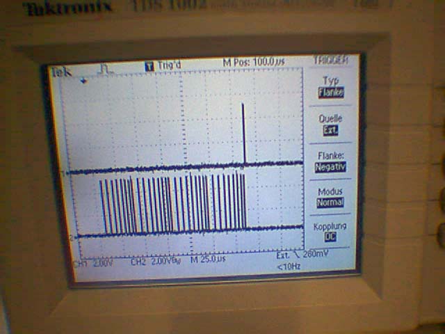
Monitoring  von Satusbytes

#ifdef STR_WORDTOBIN_USED
// *******************************************************************
char * PrintWordToBin(uint16_t u16Word)
// *******************************************************************
{
static char ucBin[18]; // Array
char * pcParser = ucBin;
uint8_t u8NN=15;
do
{
if(u8NN == 7)
    {*pcParser =' '; pcParser++;}; // Füge Lücke ein im BYTE
if(u16Word & (1<<u8NN) )
    {
    *pcParser = '1';
    }
else
    {
    *pcParser = '0';
    };
pcParser++;
}while(u8NN--);
ucBin[17]=0;
return  ucBin;
};
#endif

ANWENDUNG:
if(!strcasecmp_P( gsCmd.ucaCmd, PSTR("SS")))
    {
    uart_puts( ltoa( gu8ModeSwitchFlags, gcaStr, 10 ) );
    uart_puts_p( PSTR(" = "));
    uart_puts( PrintWordToBin(gu8ModeSwitchFlags) );
    uart_putc( 13 );
    return;
    };


Sprungliste: 74165_Input_Shift      75595_Output_Shift


Bin    Hex
0000    0
0001    1
0010    2
0011    3
0100    4
0101    5
0110    6
0111    7
1000    8
1001    9
1010    A-10
1011    B-11
1100    C-12
1101    D-13
1110    E-14
1111    F-15


//ADC_EXTERNREF_USED_ENABLED
/*
// PRESCALER 3,6864 /  32 = 115200 50-200Khz gewünscht
// REM ADC4-ADC5 = 8 BIT;
// 4+2 Channel.
//  ADC_INTERN-----ADC_INTERN-----ADC_INTERN---ADC_INTERN-----ADC_INTERN-----
*/
//****************************************************************
uint16_t ADC_10Bit(uint8_t ucChan)
//****************************************************************
{
DDRC &= ~ _BV(ucChan);   //port A Chanel Bit Input 
PORTC &= ~ _BV(ucChan); //Wegen Pullup abschalten
  // Activate ADC with Prescaler 16 --> 16Mhz/128 = 125 khz
ADCSRA = _BV(ADEN) | _BV(ADPS2) | _BV(ADPS1) |_BV(ADPS0); 
 // Select pin ADC0 using MUX
ADMUX = ucChan;
    //Start conversion
ADCSRA |= _BV(ADSC);  
while (ADCSRA & _BV(ADSC) ) // wait until converstion completed
    {
    wdt_reset();
    };      
return ADC;// get converted value
};


8051 C-compiler
http://sdcc.sourceforge.net/
http://www.rigelcorp.com/reads51.htm


Sehr interessant ! 16Bit
http://www.m16c.de/


CAN Open
Freeware
http://www.canfestival.org/
http://www.mikrocontroller.net/articles/CAN

Baudraten rechner  !
http://www.gjlay.de/helferlein/avr-uart-rechner.html

Ansteuern des  VS1011 MP3 Decoders mit dem AVR   Kosten~ 13€
http://www.spurtikus.de/basteln/vs1011.html

Ansteurn eines LCD Displays
http://www.spurtikus.de/basteln/avr-040-lcd.html

Zahlenring :
immer, wen wir eine Kreisbewegung, z.B. eine Scheibe haben und derne Position errechnen wollen, dann brauchen wir einen Zahlenring,,
der den übergang defineirt z.Zb 200 Punkt e/Rotation = 198, 199, 0, 1, 2 usw... und auhc Rückwärts... 2,1,0,199,198......
Ds geh tmit folgender Funktion im Aufruf
i16Pos = ZahlenRing(i16Pos, 200);

// Modulo mach bei MINUSWERTEN nicht -4 % 200 = NICHT 196, sondern -4, also kein Ring
// Also benötigen wir eine Zahlenringfunktion für Rotierende Positionen
// ****************************************************************
int16_t ZahlenRing(int16_t iZahl, uint16_t u16Limit)
// ****************************************************************
{
return ((iZahl + u16Limit) % u16Limit );
};
-----------------------------------------------------------------------------

// Modulo macht bei MINUSWERTEN nicht -4 % 200 = NICHT 196, sondern -4, also kein Ring
// Also benötigen wir eine Zahlenringfunktion für Rotierende Positionen
int16_t ZahlenRing(int16_t iZahl, uint16_t u16Limit)
// ****************************************************************
{
return ((iZahl + u16Limit) % u16Limit );
};


Um bei einer Scheibe die Drehrichtung zu finden, die einem Punkt auf der Scheibe näher liegt kann man z.B. so verfahren.
// *******************************************************************
void Set_SM_ShortestWayDir(void)
// *******************************************************************
{
if(    ZahlenRing( (gi16SM_Pos - giSM_TargetPoint), (int16_t)gsStMPar.u16StepsPerRotation)  >
    ZahlenRing( (giSM_TargetPoint -gi16SM_Pos), (int16_t)gsStMPar.u16StepsPerRotation)   
)
    {
    SetMotorDirection( SM_DIR_RECHTS );
    }
else
    {
    SetMotorDirection( SM_DIR_LINKS );
    };   
};

Software-UART mit avr-gcc http://www.rn-wissen.de/index.php/Software-UART_mit_avr-gcc
Zbit = F_CPU / BAUDRATE  = 16^6 / 9600 = 26666,6666  = 26,6 KZyklen pro Datenpaket = 8+2Bit = 10 Bit * 9600/ Datenpaket = 26,6KHz


In-Out Erweiterung mit  74164 universell = 74HC299 = heuet etwas ungebräuchlich..


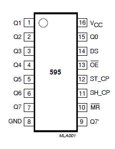
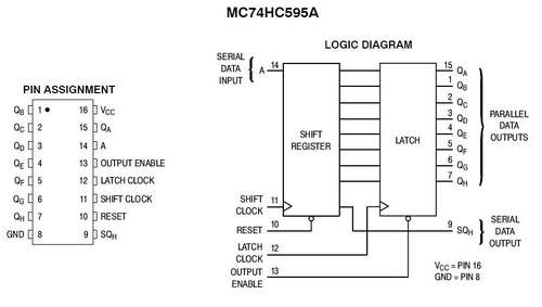
Output  Erweiterung mit 74HC(T)595
http://www.mikrocontroller.net/articles/AVR-Tutorial:_Schieberegister

WINAVR C-Module zum Download. 74595.c   74595.h

Manual - 8Bit-Shift 74HCT595.pdf
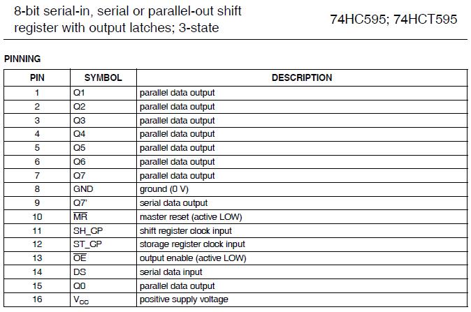
Auszug der Funktionstabelle
DS = Serial Datat Input
ST_CP= Storage Register Clock Input
/MR = Master Reset
SH_CP= Shift Clk Input
/OE = Output Enable

SH_CP & /MR=L EMPTY Shiftreg To Storagereg
SH_CP & /MR=L Ausgang 0 Stellen
SH_CP & /MR=H  Data in Shiftreg
ST_CP & /MR=H  Shiftreg to  Storagereg
ST_CP & ^ ST_CP  Pass Throug Shiftreg to Storagereg


So steht es in der PDF des 74xx595


oder, oft kommen andere Bezeichnungen für Pins von den selben IC-Typ  vor. ALso Datenbläter vergleichen 

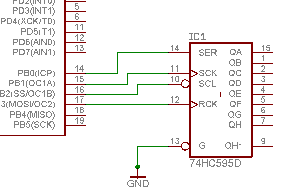
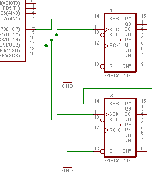
Oben ist  ST_CP = RCK = Storage ShiftRegister Clock Hgh-Low Flanke
Unten ist SH_CP = SCK = Shit Registre Clock Hgh-Low Flanken. In diesem Fall 32*l weil 4*8Bit  --4*74595


http://www.blitzlogic.com/74595_c.htm
schaltung http://www.blitzlogic.com/exp_io.htm


   74595.C  

http://www.instructables.com/id/How-to-use-a-74HC595-Shift-Register-with-a-AVR-ATt/


Pin 1 - Output B - source for LED (+)
Pin 2 - Output C - source for LED (+)
Pin 3 - Output D - source for LED (+)
Pin 4 - Output E - source for LED (+)
Pin 5 - Output F - source for LED (+)
Pin 6 - Output G - source for LED (+)
Pin 7 - Output H - source for LED (+)
Pin 8 - GND
Pin 9 - Serial Output - Carries Value from Output H to Data Pin (pin 14) of another 74HC595 to create a chain of SR's.
Pin 10 - Shift Register RESET -  Active LOW clears data in Shift Register, Latch Register is no affected.
Pin 11 - Shift Clock - LOW to HI transition shifts in data (0 or 1) from the Data Pin (pin 14). This can be toggled very fast in applications where you want a fast refresh rate like displays. I think you can toggle it on the order of 1000Hz +
Pin 12 - Latch Clock - LOW to HI transition latches the SR data to the outputs - The latch in our case will be triggered after every 8th bit is shifted in.
Pin 13 - Output Enable - Active LOW - Allows data in the Latch Register to show on the display. Typically this will be kept low, so you could just hard-wire it, but I have the AVR setup to control it. 
Pin 14 - Serial Data In (Data Pin) - Don't be scared by the word "serial". It just means digital 1 or 0 on a single pin. This is where the AVR will feed in the bits
Pin 15 - Output A - source for LED (+)  - It's a weird spot for it but it works
Pin 16 - VCC 2.0-7.0 VDC


Meine Routine

main.h
HEADER
/---------------------------------------------
// 74HC595 OPUTSHIFT SECTION
//---------------------------------------------

#define NUMBER_OF_74595        2
#define TTL74595_SERDATA_PORT        PORTB   
#define TTL74HC595_SCK_PORT        PORTB
#define TTL74HC595_RCK_PORT        PORTB
#define TTL74HC595_SCL_PORT        PORTD

#define TTL74HC595_SERDATA_BIT    0x01    //Daten rausshiften
#define TTL74HC595_SCK_BIT            0x02    //Shift clock ( LowToHigh transition )
#define TTL74HC595_RCK_BIT            0x04     // Latch Data to Output ( LowToHigh transition )
#define TTL74HC595_SCL_BIT            _BV(PD4)    //PD4 Shift Reset ( Activ Low, clearsdata ion Shift Register) eigentlich unnötig.


#define TTL74HC595_CLEARDATAINSHIFTREG()    (TTL74HC595_SCL_PORT &= ~TTL74HC595_SCL_BIT) //Clear    ShiftReg
#define TTL74HC595_ENABLEDATAINSHIFTREG()    (TTL74HC595_SCL_PORT |=  TTL74HC595_SCL_BIT)     //Enable SHiftreg

#define TTL74595_SERDATA_LOW()    ( TTL74595_SERDATA_PORT &= ~TTL74HC595_SERDATA_BIT ) //Daten rausshiften
#define TTL74595_SERDATA_HIGH()    ( TTL74595_SERDATA_PORT |= TTL74HC595_SERDATA_BIT ) //Daten rausshiften

#define TTL74HC595_SCK_LOW()    ( TTL74HC595_SCK_PORT &= ~TTL74HC595_SCK_BIT ) //Shift clock
#define TTL74HC595_SCK_HIGH()    ( TTL74HC595_SCK_PORT |= TTL74HC595_SCK_BIT ) //Shift clock

#define TTL74HC595_RCK_LOW()    ( TTL74HC595_RCK_PORT &= ~TTL74HC595_RCK_BIT ) // Latch Data to Output
#define TTL74HC595_RCK_HIGH()    ( TTL74HC595_RCK_PORT |= TTL74HC595_RCK_BIT ) // Latch Data to Output


MAIN.C
//GLOBAL
uint8_t gu8aTTL74595[ NUMBER_OF_74595 ];// Gobales Array mit Bytezahl der benutzen Shiftregister

// *******************************************************************
void Write_OUT74HC595( uint8_t * pca74HC595 )  // mit pointer auf array
// *******************************************************************
{
uint8_t u8NN;
uint8_t u8AA; // 74595 Cnt
TTL74HC595_CLEARDATAINSHIFTREG(); //Diese Leitung Könnte auch immer High sein.
_delay_us(1);
TTL74HC595_ENABLEDATAINSHIFTREG();
TTL74HC595_SCK_LOW();
TTL74HC595_RCK_LOW();
_delay_us(1);
u8AA = NUMBER_OF_74595 -1;
do
    {
    u8NN = 7;
    do
        {  // Clock out bits from the eo array
         if( pca74HC595[u8AA] & (1UL << u8NN) )     // Ist es undiert eine EINS ?
            {     
            TTL74595_SERDATA_HIGH();    
            }         
         else
            {   
            TTL74595_SERDATA_LOW();   
            };     

        _delay_us(1);
        TTL74HC595_SCK_LOW(); //Shift clock
        _delay_us(1);
        TTL74HC595_SCK_HIGH();    //Shift clock
      }while( u8NN-- );
    }while(u8AA--); 

TTL74HC595_RCK_HIGH(); // Latch Data to Output
};

Anwendung mit LED Shift Modul...


Input Shift Register  74 HCT 165
WINAVR  C-Module  zum Download...In74165.c  In74165.h


...mit Auszug  wie der Chip Kaskadiert und angeschlossen wird

http://www.blitzlogic.com/74165_c.htm

   74165.C
74165 Library Routine to expand no. of input lines


///////////////////////////////////////////////////////////////////////////
//// Library for a 74165 Expanded Input Chip ////
//// ////
//// Any number of these chips may be connected in series to get ////
//// 8 additional inputs per chip. The cost is 3 I/O pins for ////
//// any number of chips. ////
//// ////
//// read_expanded_inputs(ei); Reads the array ei from the chips ////
//// ////
///////////////////////////////////////////////////////////////////////////
//// (C) Copyright 1996,1997 Custom Computer Services ////
//// This source code may only be used by licensed users of the CCS C ////
//// compiler. This source code may only be distributed to other ////
//// licensed users of the CCS C compiler. No other use, reproduction ////
//// or distribution is permitted without written permission. ////
//// Derivative programs created using this software in object code ////
//// form are not restricted in any way. ////
////////////////////////////////////////////////////////////////////////////

#IFNDEF EXP_IN_ENABLE

#define EXP_IN_ENABLE PIN_B3
#define EXP_IN_CLOCK PIN_B4
#define EXP_IN_DI PIN_B5
#define NUMBER_OF_74165 1

#ENDIF


void read_expanded_inputs(byte *ei) {
byte i;

output_high(EXP_IN_CLOCK);
output_low(EXP_IN_ENABLE); // Latch all inputs
output_high(EXP_IN_ENABLE);

for(i=1;i<=NUMBER_OF_74165*8;++i) { // Clock in bits to the ei structure
shift_left(ei,NUMBER_OF_74165,input(EXP_IN_DI));
output_low(EXP_IN_CLOCK);
output_high(EXP_IN_CLOCK);
}
output_low(EXP_IN_ENABLE);
}


30.08.2011
Trick für Zusamenfügung von 8 Bit  breiten LSB MSB  Registern
zu einem 16 oder 32 Bitbreiten Register
 und damit  zu einem anderen Datentyp der die Bitbreite representiert.

Das geht mit der struktur union:
//-------------------------------------------------------------------
typedef union
    {
    uint8_t u8CntVal[4]; // LSB MSB LSB MSB LSB MSB
    uint32_t u32Counter_Val;
    }COUNTERVAL_TYPE;
//-------------------------------------------------------------------
COUNTERVAL_TYPE gstuCounterVal_0;  //nstanz
//-------------------------------------------------------------------
//in Main

//TEST
gstuCounterVal_1.u8CntVal[0] = 17;  // 0x11
gstuCounterVal_1.u8CntVal[1] = 34;    //0x22
gstuCounterVal_1.u8CntVal[2] = 68;    //0x44
gstuCounterVal_1.u8CntVal[3] = 136;    //0x88
PrintULongCR( gstuCounterVal_1.u32Counter_Val );
//-------------------------------------------------------------------
Ergebniss  => 2286166545 = 0x88442211  sind 32 Bit breite
Also hat die Einfügung der Zahlen in  die Union mit Typewandlung geklappt. !


USB nach I2C-Adapter mit ATMEL
http://www.harbaum.org/till/i2c_tiny_usb/index.shtml

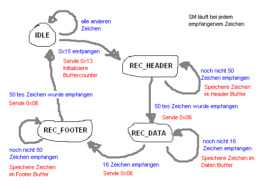
Zustandsautomat odetr Stamaschine = ST-- UART Konzept
http://de.wikipedia.org/wiki/Endlicher_Automat
http://www.mikrocontroller.net/articles/Statemachine
das Prinzip ist, dass du mit jedem empfangenen Byte guckst, was du
damit anfangen kannst. Wenn dieses Byte dazu führt, dass du
(basierend auf dem aktuellen Zustand des Automaten) einen bestimmten
Abschnitt des Headers jetzt erkannt hast, dann schaltet der
Automat weiter und guckt, was danach kommt. Auf diese Weise
hangelt man sich Stück für Stück weiter. Wenn irgendetwas
unerwartetes im Datenstrom ankommt, bricht der Zustandsautomat
(so der offizielle deutsche Name) ab und fällt auf den Grundzustand
zurück.


ENC28J60 ist ein Ethernet-Controller von Microchip
NC28J60
Verbaut im AVR NET-IO
http://www.mikrocontroller.net/articles/ENC28J60
Ethnernetmodul für AVR
Der ENC28J60 ist ein Ethernet-Controller von Microchip
Inzwischen gibt es einen Nachfolger, den ENC624J600.

RJ45 Stecker mit Übertrager: RJLD-043TC
http://www.ulrichradig.de/  

Ethernet ATmega32/644 Experimentierboard    Kamera fürs ETH_M32/644_EX

Inzwischen ist es auch möglich eine Philips DC-3840 anzuschliessen