Zurück
(C) Christof Ermer, Regensburg
30.05.2016
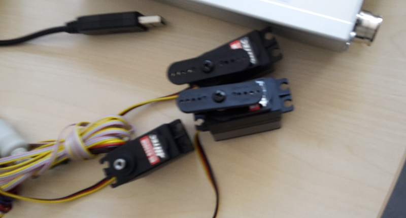
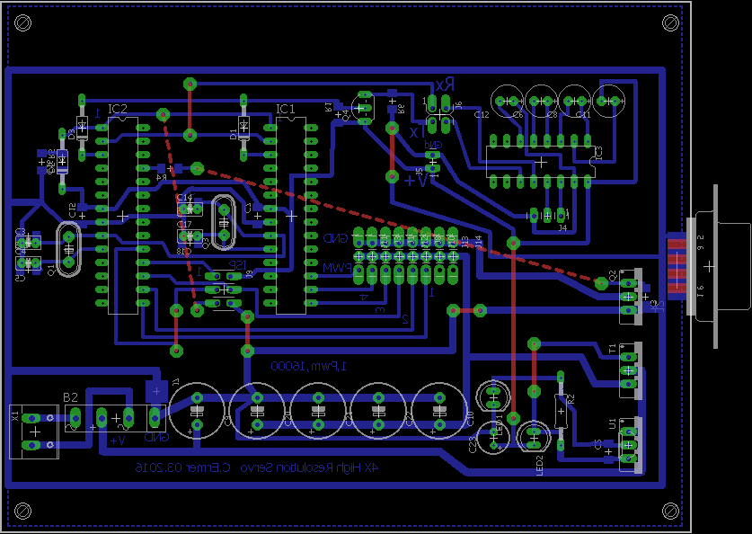
4x-MultiServo
Dokumenation. +
Software.
ATM16_V1.0-2011_MultiSinus_PWM.zip
Eagle
Eagle_4xServo_HighRes.zip
//------------------------------------------------------------------------------
// Programmed by Christof Ermer
//------------------------------------------------------------------------------
/*
C:\AVR_Projekte\AA_AVR_PRJ_2016\ATM8-2x-16BitTimerMultiPWM_Portdirect - 2te_MCU
MCU2 = EXTERN CLOCK
FUSE HIGH = 0xA0
FUSE LOW = 0xDF
_MCU1 =
FUSE HIGH = 0xBF
FUSE LOW = 0xCF
TIMER 0 = TICK
TIMER 1 = 16 BIt PWM
TIMER 2 = Manage TImer 1
Processor 1 = links
#define UART_BAUD_RATE 9600
*/
//#define TICK_USED
#define MULTI_PWM_USED
//#define UART_IS_USED
//http://www.engbedded.com/fusecalc/
// Low Fuse=0xBF High Fuse= 0xCF
//alternate Low Fuse=0x9E High Fuse= 0xEF
#define AUTOR "Christof Ermer"
#define DATUM "29.04.2016"
#define UHRZEIT "12:00"
#define HARDWARE "AVR ATMega8 Board"
#define SOFTWARE "2x16Bit HighResolution PWM"
#define SHOW_BAUDRATE "19200,8,N,1"
#include <ctype.h>
#include <inttypes.h>
#include <avr\io.h>
#include <avr\pgmspace.h> // <--#include <progmem.h>
#include <stdio.h>
#include <math.h>
#include <stdlib.h>
#include <stdarg.h>
#include <string.h>
#include <avr\interrupt.h> // obsolete #include <avr\signal.h>
#include <avr\wdt.h>
//Produziert Fehler...
#include <util\delay.h> //_delay_loop_1 _delay_loop_2 delay_ms
#include "avr_register.h" //with Hardware assigns
#include "main.h" //witdh Hardware assigns
#include "uart.h"
#include "TxtFunc.h"
#include "debug.h"
//CONSTANT ARRAYs IN .TEXT = ROM ARREA .DATA IST SRAM !! .BSS SRAM
//const char MCA_DELIMTERSTR[] PROGMEM = { ',',0 };
volatile uint32_t gu32_Ticks; //T2 timeCounter, only NN_Counter for Keypressings
//uint8_t g16PWM_Compare = 40U;
float gf_PWM_Delay ;
//T_BAUDRATE eBaud = 57600;
uint8_t gu8Mode;
volatile uint8_t gu8Status;
// ****************************************************************
ISR( TIMER2_OVF_vect ) //oder SIGNAL--INTERRUPT(SIG_OVERFLOW2) = mit SEI am Anfang
// *******************************************************************
{ //~1µS
volatile unsigned char u8Sreg = SREG;
volatile static uint8_t u8Periode;
cli();
u8Pede++;
u8Periode %rio= 5;
if( !(u8Periode) ) // 1/5
{
INIT_PWM_DIR();
TCCR1B = 0; //STOP T1
TCCR1A = 0 ;
TCNT1=0;
SET_OC2_HIGH(); // OC1X alle HIGH
SET_PWMS_HIGH(); //PWM ALLES ON
// TCCR1A = (1<<COM1A1) | (1<<COM1B1); //Clear OC1A OC1B on compare
TIFR |= (1<<OCIE1A) | (1<<OCIE1B); // Flag weg !!!!!!!!!!!!!!!!!!!!!
TIMSK |= (1<<TOIE0) | (1<<TOIE2) | (1<<OCIE1A) | (1<<OCIE1B); //INT T2 und INT T1A
TCCR1B = (1<<CS10); // :1 NORMAL
};
SREG = u8Sreg;
};
// *******************************
ISR( TIMER1_COMPA_vect )
// *******************************
{
volatile unsigned char u8Sreg = SREG;
cli();
PWM_PORT &= ~(1<<PWM_A_16BIT_PIN);
TIMSK &= ~(1<<OCIE1A);
SREG = u8Sreg;
};
// *******************************
ISR( TIMER1_COMPB_vect )
// *******************************
{
volatile unsigned char u8Sreg = SREG;
cli();
PWM_PORT &= ~(1<<PWM_B_16BIT_PIN);
TIMSK &= ~(1<<OCIE1B);
SREG = u8Sreg;
};
//TCKcounter ! /1024 = 61/Sekunde
// ****************************************************************
//volatile SIGNAL(TIMER2_OVF_vect) //oder SIGNAL--INTERRUPT(SIG_OVERFLOW2) = mit SEI am Anfang
ISR( TIMER0_OVF_vect ) //TIMER0_COMP_vect oder SIGNAL--INTERRUPT(SIG_OVERFLOW0) = mit SEI am Anfang
// *******************************************************************
{
volatile unsigned char u8Sreg = SREG;
volatile static uint32_t u32Now;
cli();
gu32_Ticks++;
if( (gu32_Ticks - u32Now) > 61)
{
u32Now = gu32_Ticks;
gu8Status |= TICK_EVENT;
}; // Tickcounter
UART_TXRX_Check(); //IMMER VORHANDEN !! IN ALLEN LOOPS DIE ZEIT BRAUCHEN
/*
if( !(gu32_Ticks % 10) )
{
};
*/
SREG = u8Sreg;
};
//TIMER2
// *************************************
void StartTimers(void) //0.1 Seconds interrupt
//Normal MODE OC2 Disconnect Prescale 64
// *************************************
{
volatile unsigned char u8Sreg = SREG;
cli();
CLR_ENABLE();
INIT_ENABLEPIN();
INIT_PWM_DIR();
INIT_OC2DIR();
OCR1A = PWM_MITTE;
OCR1B = PWM_MITTE;
OCR2 = OCR2_MITTE;
TCNT1=0;
TCCR1A = 0;
TCCR1B = 0; // Da ist der Clock drin
// 8 Bit Timer erzeugt 244 HZ Und OC2 CLEARCOmpare
TCNT2=0;
TCCR2 = (1 << CS22) | (1 << CS21); //256
//TCCR2 = (1 << CS22) | (1 << CS21) | (1 << COM21); //256 OC2 CLEAR ON COMPARE //OC2=PB3 Toggle, NORMAL
TIFR |= (1<<TOV2);
TIMSK |= (1<<TOIE2) | (1<<TOIE0); //(1<<OCIE2); //INT T2 und INT T1A
SREG = u8Sreg;
};
// *************************************
void StartTickTimer(void) //244 INT/Sec
// *************************************
{
unsigned char sreg = SREG;
TCCR0 = (1<<CS02) | (1<<CS00); //1024
SREG = sreg; //loakaler Speicher
sei();
};
#ifdef UART_USE_ENABLED
// *******************************************************************
void CheckOrder(char *pcStrOrder) //von gcaRxStr
// *******************************************************************
{
// zerlege UART RX Str inseine Delimitrer Bestandteile
TokensRXStr( pcStrOrder ); //und lege diese in gsCmd.ucaCmd ab
if( !strcasecmp_P( gsCmd.ucaCmd, PSTR("PWM3") ) )
{
OCR1A = (uint16_t)gsCmd.fCmdVal_1;
return;
};
if( !strcasecmp_P( gsCmd.ucaCmd, PSTR("PWM4") ) )
{
OCR1B = (uint16_t)gsCmd.fCmdVal_1;
return;
};
if( !strcasecmp_P( gsCmd.ucaCmd, PSTR("PON") ) )
{
SET_ENABLE();
gu8Mode |= MODE_ACTIVE;
return;
};
if( !strcasecmp_P( gsCmd.ucaCmd, PSTR("POFF") ) )
{
CLR_ENABLE();
gu8Mode &= ~MODE_ACTIVE;
return;
};
if( !strcasecmp_P( gsCmd.ucaCmd, PSTR("STAT3") ) )
{
PrintULongCR(OCR1A);
return;
};
if( !strcasecmp_P( gsCmd.ucaCmd, PSTR("STAT4") ) )
{
PrintULongCR(OCR1B);
return;
};
if( !strcasecmp_P( gsCmd.ucaCmd, PSTR("ENABLE") ) )
{
if( (uint8_t)gsCmd.fCmdVal_1)
{
SET_ENABLE();
gu8Mode |= MODE_ACTIVE;
}
else
{
CLR_ENABLE();
gu8Mode &= ~MODE_ACTIVE;
};
return;
};
if( !strcasecmp_P( gsCmd.ucaCmd, PSTR("DD") ) )
{
gf_PWM_Delay = gsCmd.fCmdVal_1;
return;
};
if( !strcasecmp_P( gsCmd.ucaCmd, PSTR("SIN") ) )
{
if( (uint8_t)gsCmd.fCmdVal_1)
{
gu8Mode |= MODUS_SINUS;
}
else
{
gu8Mode &= ~MODUS_SINUS;
};
return;
};
if( !strcasecmp_P( gsCmd.ucaCmd, PSTR("PING2") ) )
{
Print_PStrCR( PSTR("Pong") );
return;
};
if( !strcasecmp_P( gsCmd.ucaCmd, PSTR("Device2") ) )
{
Print_PStrCR( PSTR("High-Resolution PWM") );
return;
};
if( !strcasecmp_P( gsCmd.ucaCmd, PSTR("TT2") ) )
{
PrintLongCR( gu32_Ticks );
return;
};
if( !strcasecmp_P( gsCmd.ucaCmd, PSTR("RR2") ) )
{
gu32_Ticks = 0; //Reset TickCounter
return;
};
if( !strcasecmp_P( gsCmd.ucaCmd, PSTR("EE2") ) )
{
if( (uint8_t)gsCmd.fCmdVal_1)
{
gu8Mode |= TX_TRAFFIC_ON;
}
else
{
gu8Mode &=~ TX_TRAFFIC_ON;
};
return;
};
if( !strcasecmp_P( gsCmd.ucaCmd, PSTR("??2") ) )
{
uart_puts_p( PSTR("x=1,2,3,4,PWMx,PON,POFF,Enable{0,1},DD,SIN{0,1},STAT2\r") );
uart_puts_p( PSTR("??2,Device2,TT2,EE2{0,1},RR2,BAUD2,PING2,DD\r") );
return;
};
if( !strcasecmp_P( gsCmd.ucaCmd, PSTR("BAUD2") ) )
{
uart_init( UART_BAUD_SELECT((uint16_t)gsCmd.fCmdVal_1, F_CPU) );
ResetRxBuff();
return;
};
};
#endif
// **********************************
int main(void)
// **********************************
{
cli();//The global interrupt flag is maintained in the I bit of the status register (SREG).
//INIT HARDWARE
//USing of PORTOUTS 1=OUT, 0=IN
DDRB = 0x00;
DDRC = 0x00;
DDRD = 0x02; //TX
ADCSR |= (1<<ADC); //ADC OFF
INIT_ENABLEPIN();
INIT_OC2DIR(); //| (1<<OC1A) | (1<<OC1B)
INIT_PWM_DIR();
//SFIOR = (1<<PUD); //Pullup Disable
//Pointer and Strings init
wdt_enable(WDTO_1S); //WDTO_500MS
wdt_reset(); //WATCHDOG!!!!!!!!!!!!!!!!!!!!!!!!!!!!!!!!!!
// Initialize UART library, pass baudrate and avr cpu clock
// with the macro UART_BAUD_SELECT()
//#ifdef UART_IS_USED
uart_init( UART_BAUD_SELECT(UART_BAUD_RATE, F_CPU) );
ResetRxBuff();
sei();
Print_PStrCR( PSTR(HARDWARE) );
Print_PStrCR( PSTR(SOFTWARE) );
Print_PStrCR( PSTR(AUTOR) );
Print_PStrCR( PSTR(DATUM) );
uart_puts_p( PSTR("UART-Baud="));
Print_PStrCR( PSTR(SHOW_BAUDRATE) );
//#endif
OCR1A = PWM_MITTE;
OCR1B = PWM_MITTE;
StartTickTimer(); //8 Bit Timer 2 = MS Tick Counter
StartTimers();
SET_ENABLE();
gu32_Ticks = 0;
//PWM_PORT |= PWM_ENABLE_BIT;
gf_PWM_Delay = 0.1;
//gu8Mode |= MODUS_SINUS;
gu8Mode = 0;
// ************ MAIN LOOP FOR EVER *********************
sei();
for (;;) /* loop forever */ //Aber schnell > 200.000 mal/Sekunde
{
sei();
wdt_reset(); //WATCHDOG!
if( gu8Mode & MODUS_SINUS)
{
uint16_t u16PWMVal;
Toggle_Bit(2);
_delay_ms( gf_PWM_Delay );
u16PWMVal++;
u16PWMVal %= (PWM_1MS-1); //OCR1A = PWM_1MS + u16PWMVal ;
OCR1A = PWM_1MS + round( 8000U + 8000U * sin( 2.0 * M_PI * (u16PWMVal / 16000.0) ) );
OCR1B = OCR1A;
};
if( gu8Status & TICK_EVENT )
{
gu8Status &= ~TICK_EVENT;
Toggle_Bit(1);
if( gu8Mode & TX_TRAFFIC_ON )
{
Toggle_Bit(3);
ULongToNumStr( gu32_Ticks );
uart_puts( gcaNumStr );
uart_puts_p( PSTR(", ") );
ULongToNumStr( OCR1A );
uart_puts( gcaNumStr );
uart_puts_p( PSTR(", ") );
PrintLongCR( OCR1B );
};
//PrintStrCR( ByteToBin (TIMSK) );
}; // Tickcounter
}; //main loop Ende
};
// ******************* MAIN END ********************************************
================================================================
#ifndef MAIN_HEADER //Prevents multiple includes
#define MAIN_HEADER
//#define UART_BAUD_RATE 9600
//#define UART_BAUD_RATE 57600U
#define UART_BAUD_RATE 19200U
#define TIMER_TICK_USED
#define DISABLE_ALL_PULLUP() (SFIOR |= _BV(PUD));
#define ENABLE_ALLUP_SCL() (SFIOR &= ~(_BV(PUD)));
#define WDTO_2S 7 //WatchDog
//========================================================================
//TIMERS
//TIMER2 = is 61 miliseconds Timer ~approx.
// 16MhZ / 1024 / 256 = 61,03515625 Hz
// T= 1/f = 0.016384 ms / Interrupt
//Aufzaehlbezeichner
#define RX_BITNR PD0 //0
#define TX_BITNR PD1 //1
extern volatile uint32_t gu32_Ticks; // T2 timeCounter, only NN_Counter for Keypressings
extern void CheckOrder(char *pcStrOrder); //von gcaRxStr
#ifdef TIMER_TICK_USED
void StartTickTimer(void); //0.1 Seconds interrupt
#endif
// SOFT PWM
#define ENABLE_DDRX DDRC
#define ENABLE_PORT PORTC
#define ENABLE_PIN 2
#define INIT_ENABLEPIN() (ENABLE_DDRX |= (1<<ENABLE_PIN))
#define SET_ENABLE() (ENABLE_PORT |= (1<<ENABLE_PIN))
#define CLR_ENABLE() (ENABLE_PORT &= ~(1<<ENABLE_PIN))
#define CLR_PWM_OC1A_PIN() (PWM_PORT &= ~(1<<PWM_A_16BIT_PIN))
#define CLR_PWM_OC1B_PIN() (PWM_PORT &= ~(1<<PWM_B_16BIT_PIN))
#define PWM_DDRX DDRB
#define PWM_PORT PORTB
#define PWM_A_16BIT_PIN 1
#define PWM_B_16BIT_PIN 2
#define INIT_PWM_DIR() (PWM_DDRX |= (1<< PWM_A_16BIT_PIN) | (1<< PWM_B_16BIT_PIN))
#define SET_PWMS_HIGH() (PWM_PORT |= (1<<PWM_A_16BIT_PIN) | (1<<PWM_B_16BIT_PIN))
#define OC2DDRX DDRB
#define OC2PORT PORTB
#define OC2 3
#define INIT_OC2DIR() ( OC2DDRX |= (1<<OC2) )
#define SET_OC2_HIGH() ( OC2PORT |= (1<<OC2) )
#define SET_OC2_LOW() ( OC2PORT &=~(1<<OC2) )
#define PWM_1MS 16000U
#define PWM_MITTE 24000U
#define PWM_2MS 32000U
#define OCR2_MITTE 127
#define MODUS_SINUS 0x01
#define MODUS_SINGEL_PULSE 0x02
#define MODE_ACTIVE 0x04
#define MODE_FALLBACK 0x08
#define TX_TRAFFIC_ON 0x10
//gu8Mode
#define TICK_EVENT 0x01
//volatile uint8_t gu8Status;
extern float gf_PWM_Delay ; // für sinus
#endif //MAIN_HEADER
 (C) Christof Ermer,
Regensburg
(C) Christof Ermer,
Regensburg