
FUNK Allerlei
SIEHE Funk_Frequenzen
SDRsharp_Das_große_Buch_v5.5.pdf 02.09.26
Siehe auch SDR
#PMR_Frequenzen
AMATEURFUNK REGENSBURG
https://www.darc.de/der-club/distrikte/u/ortsverbaende/13/relais/
Unser Club-Rufzeichen: DL0RA
Der Deutschland- sowie der Bayern-Ostrundspruch
wird immer am Donnerstag um 19:00 Uhr von DL0RA ueber die Relaisstellen
DB0TK sowie DB0RP gesendet!
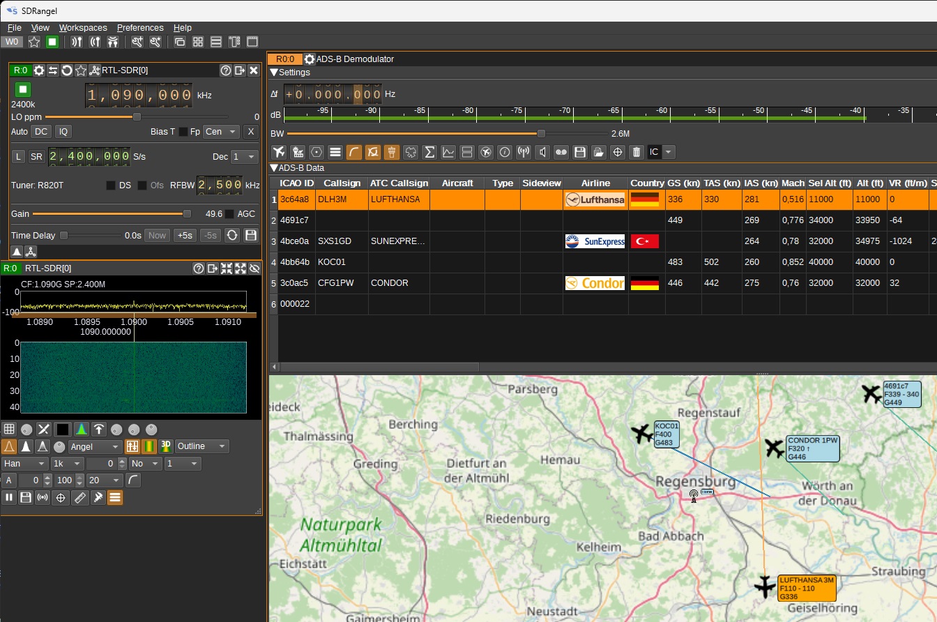
Flugzeug Position abhören ADS-B Empfang mit RTL-SDR & SDRangel
https://www.youtube.com/watch?v=fZyAyjtr4Qg&t=946s
Antenne: Dipol Schenkel basteln, mit 2x7,5cm, Seknrect Plaisiert
1,090 KHz
NanoVNA #02 📈 Betrieb & Einstellungen des Antennen Analyzers
https://www.youtube.com/watch?v=DkGSNeU5MqU&t=928s
Flugzeug Position abhören ADS-B Empfang mit RTL-SDR & SDRangel
https://www.youtube.com/watch?v=fZyAyjtr4Qg&t=946s
Antenne: Dipol Schenkel basteln, mit 2x7,5cm, Seknrect Plaisiert
1,090 KHz
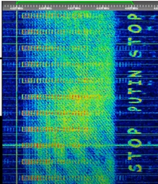
STOP PUTIN
Dies habe ich auf Kurzwelle, 4625 KHz, USB, Russische Buzzer Frequenz.
Jemand hat das überlagert und die Frequenz so moduliert, dass die
Schrift STOP PUTIN in einem
SDR Wasserfall Diagramm
erscheint.
Sowas kann nur jemand lesen, der SDR Wasserfall Diagramm
Software hat und kennt.
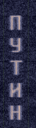
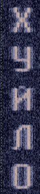
Ein anderer Sender: hier der Link zu dem Wasserfall Diagram mit dem "Putin is a dickhead"
Text:
https://www.reddit.com/r/RTLSDR/comments/16gjr62/russian_waterfall_text_from_space/


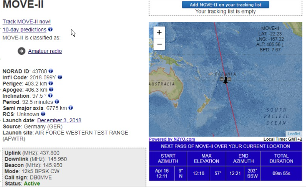
MOVE
II nach 7 Jahren immer noch im All und Transceiver von mir Senden auch
(Morsecode auf 145.950 MHz beim Überflug empfangbar
https://www.n2yo.com/satellite/?s=43780#google_vignette
https://www.n2yo.com/satellite/?s=43780&fbclid=IwY2xjawJsa8pleHRuA2FlbQIxMAABHvrNYpFu6tYJvHALe_EC4oakT12t8Ut5MgsKIHUY0YWFhj1fE04yI1pm8j1H_aem_gBGAfgiLjA2BdbDTFZXjOg#google_vignette
Raumstation
https://www.n2yo.com/satellite/?s=25544
PMR Frequenzen (70 cm)
12,5 KHz Raster
Kanal Frequenz in MHz Nutzung
(Inoffiziell)
Kanal FM Mittenfrequenz in
MHz Kanalbreite/Kanalraster in kHz
( Baofong will einen PUNKT in der Frequenzangabe, also 446.00625.
1
446,00625 12,5
2
446,01875 12,5
3
446,03125 12,5
4
446,04375 12,5
5
446,05625 12,5
6
446,06875 12,5
7
446,08125 12,5
8
446,09375 12,5
9
446,10625 12,5
10
446,11875 12,5
11
446,13125 12,5
12
446,14375 12,5
13
446,15625 12,5
14
446,16875 12,5
15
446,18125 12,5
16
446,19375 12,5
BSp:
1 446,00625 Standardfrequenz,
unterstützt von jedem Gerät, immer Kanal 1
2 446,01875 Geocachingkanal
3 446,03125
4 446,04375 Bei
Dreikanal-PMR-Funkgeräten Kanal 2.
In Regensburg werden Taxifunker
im Allgemeinen Frequenzen aus den
Bereichen 146-174 MHz und 440-470 MHz verwendet. Es gibt 9
Frequenzzuteilungsgebiete in jedem Bereich, wobei das 146-174 MHz Band
9 Frequenzen pro Gebiet und das 440-470 MHz Band 3 Frequenzen pro
Gebiet bietet.
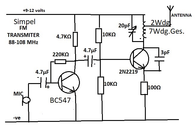
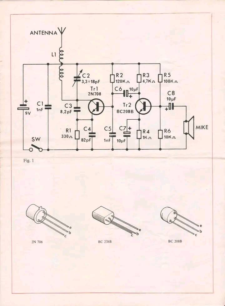
Simple UKw Transceiver Schematic
So um die 1977 habe ich genau diese Schaltung mit Erfolg
aufgebaut. Mit in Europa gängigen Transistoren. Für die Spule 7
Windungen Silberdraht um eine Bleistift gewickelt. Aber mit
zusatzlichen 2 separaten Windungen im Spulenraum um die Antenne
zu adaptieren. Mit Wachs fixiert. Keramik Mini Drehkondensator. Eine
alte, schöne UKW Taschenradio Antenne darauf, 9 Volt Batterie,
Mikrofonkapsel, Ein kleines Kästchen. Fertig war der UKW Sender. Die
Frequenz war nicht besonders Temperatur stabil. Kein Problem
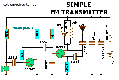
EDIT: COIL DETAILS
4 and a half turns on a half inch diameter former and the tap of the
antenna taken from the 3rd turn.
During my early days of involving with electronics , end of ‘70s, the
most important goal of me and my buddies was how to build any kind of
transmitter. The information was very little at the time.
So when a friend found this circuit diagram on the blackboard of a
college, I was very exited. I remember that I built the first prototype
on the first PCB that I etched. It worked fine. The
neighbours were very happy listening to all of us communicating on the
FM frequencies.
I had the chance to experiment a lot with this design. I replaced the
2N2219 oscillator transistor with a BD139 on a heatsink and I supplied
the unit with 24 volts. I had I simple dipole antenna connected to it
but I was living on a 3 storey building so the antenna was something
like 10-12 meters from the ground. I achieved a range of more than 5
Km.
It was the time that pirate stations were very popular. And I got to be
very famous in my town . Especially after I built some very powerful
valve transmitters. The people were very happy having some alternative
stations to listen music from. But the police were not that happy.
We had a sad ending to this but it’s a whole other story.
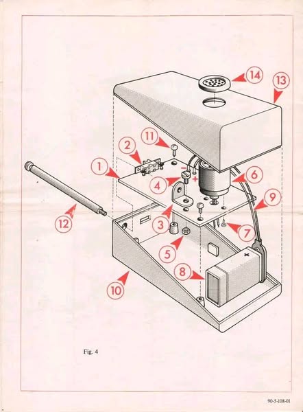
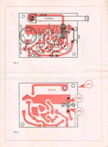
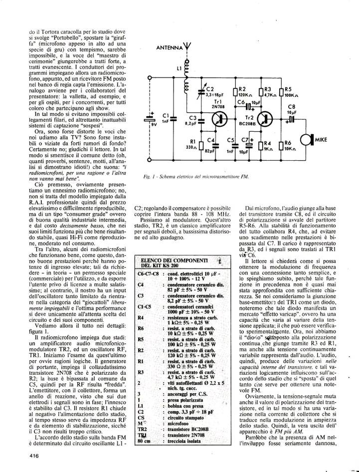
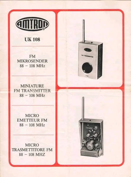
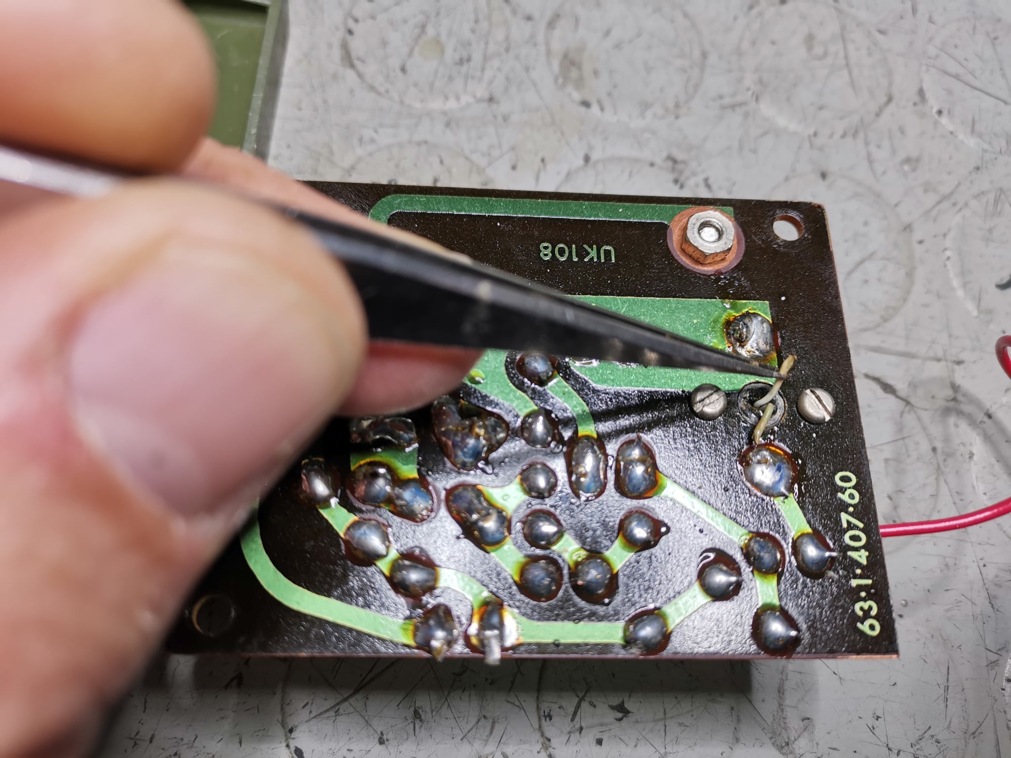
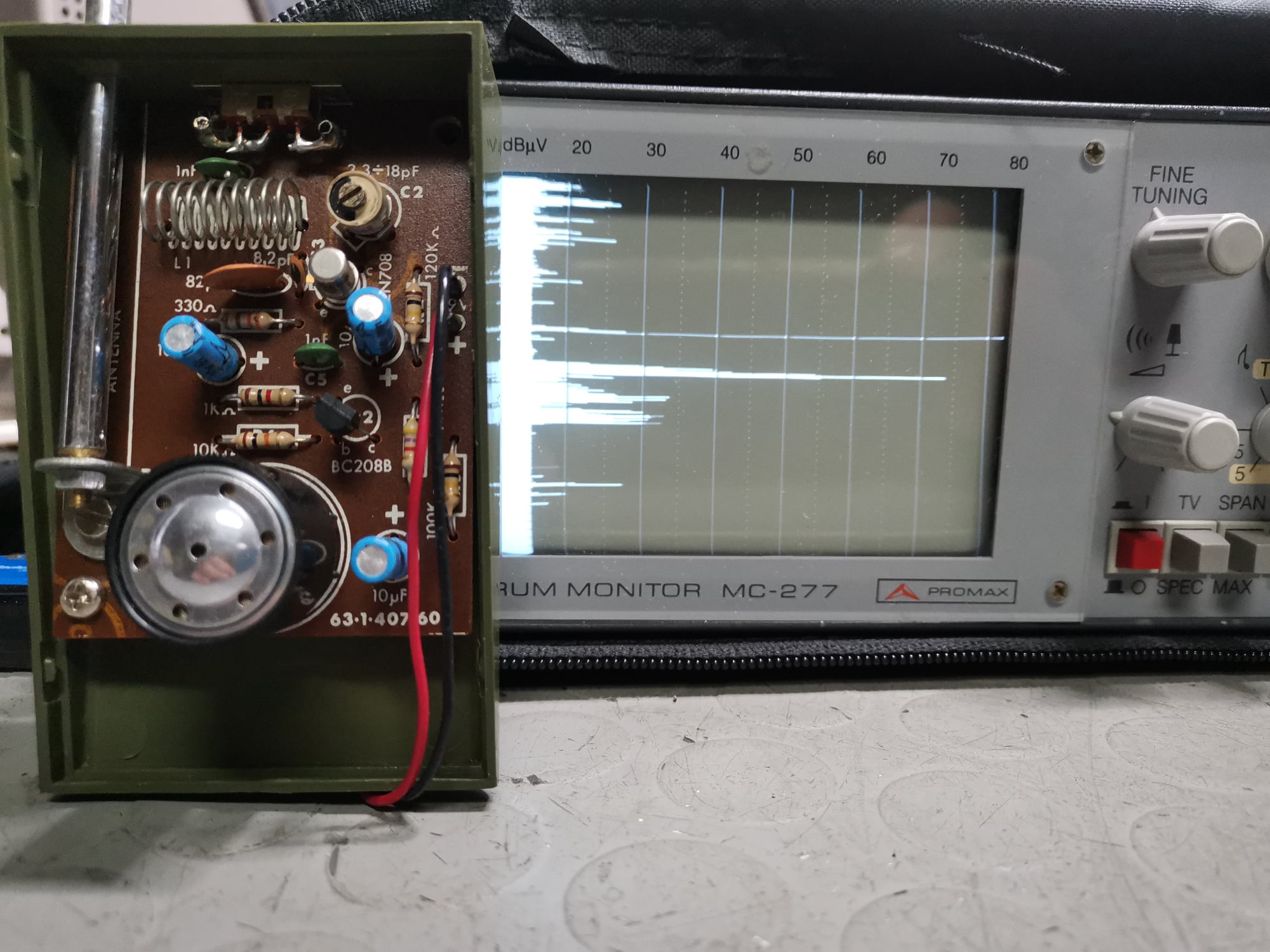
AMTROM UK 108
https://www.facebook.com/search/top?q=amtron%20uk108
https://www.facebook.com/media/set/?vanity=maurotecnico&set=a.10220889525208719
88-108MHz_FM_TRansmitterCircuit_4
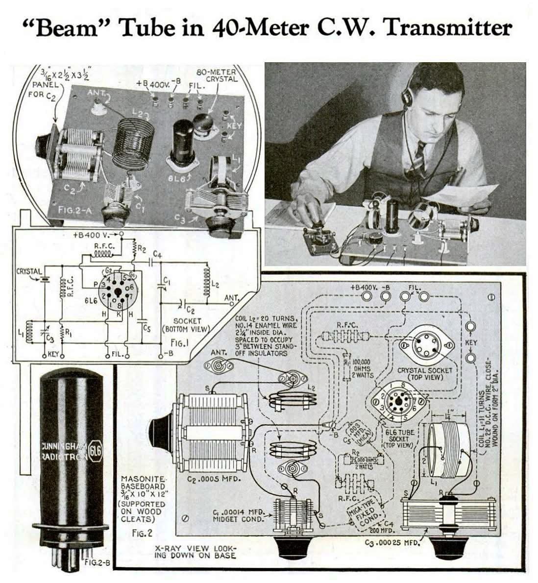
1937 Beam Tube 40 Mtr Transmitter.
88 years ago, this set appear in in the July 1937 issue of Popular
Mechanics.
Modern as the metal tube,this 40 meter crystal controlled transmitter
is especially designed for the beginner and had a range of about 500
Miles.
The 6L6 serves as a “tritet” crystal oscillator using a 80 meter
crystal and doubling to 40 meters in the plate circuit.
(Use a low-pass filter on the output if you’re actually going on-air
harmonics can be nasty and get you unwanted attention from the FCC or
your neighbors!.)
 (C)
Christof Ermer, Regensburg
(C)
Christof Ermer, Regensburg